|
|
|
ALLIED BOMBS AND FUZES |
| BRITISH FUZES |
|
FUZE DATA |
FILE NO.: 2211.N2 |
|
NATIONALY: BRITISH |
INFORMATION DATE: October 1942 |
|
DESIGNATION |
PRINCIPAL MARKING |
D.A. No. 13 Mark I |
|
D.A. No. 13 |
|
|
|
Mark I |
CLASSIFICATION |
Mechanical Nose Impact |
|
|
TYPE OF MISSILE |
Bomb, Aircraft, H.E.S.N. Mark II |
|
MARKINGS AND |
|
BOMBS USED IN: |
|
SUBSIDIARY |
|
Used only in the nose of the Bomb, Air- |
|
MARKINGS: |
|
craft, H.E.S.N. Mark II |
|
|
|
|
DATA |
D.A. No. 13 |
|
|
1 |
COLOR |
Brass |
|
|
2 |
OVERALL LENGTH |
14.7 inches (less booster) |
|
|
3 |
OVERALL WIDTH |
2.6 inches |
|
|
4 |
DIAMETER OF VANES |
5.0 inches |
|
5 |
MATERIAL OF CONSTRUCTION |
Brass collar and vanes, steel tube and plunger rod. |
|
6 |
DESCRIPTION |
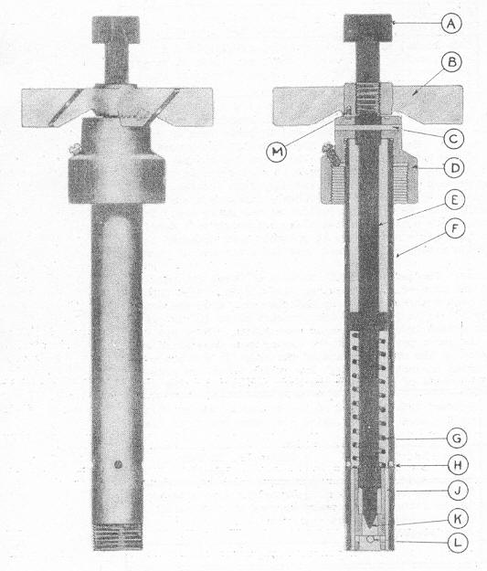
This fuze consists of a steel tube (F) with the lower end threaded to screw into an adapter. A bushing is pressed into the lower end of tube (F) and serves as a guide to the plunger rod (E). The tube also has four gas escape grooves (J) and two gas escape holes (H). The top of tube (F) screws into the brass body collar (D). This collar is threa- ded to screw over the central tube of the bomb and to re-ceive the upper end of the tube (F). A small set screw in the collar (D) prevents it from unscrewing from the central tube of the bomb. The plunger rod (E) is made of steel and terminates in the striker (K). There is a collar approximately half-way along the plunger rod which serves as a base for the creep spring (C). The upper end of plunger rod (E) is threaded in two places; the lower threads carry the arming vanes (B), and the upper threads the plunger cap (A). The arming vanes (B), of which have there are six blades, are made of cast brass. There is a vane stop screw (M) fixed to the under side of the vane boss. |
|
|
Safety Devices: - The shearing wire (C) is 5/32 inch in dia-meter, and passes through the body collar and the plunger. The creep spring (G) fits between collar on plunger rod and inner side of the plunger rod bushing. The arming vanes (B) are kept from turning during the flight of the plane by the safety pin clip. |
|
|
7 |
POSITION AND METHOD OF FIXING IN BOMB |
Screwed into the end of the central tube of the bomb, and held in place by a set screw. |
|
8 |
FUZES LIKELY TO BE FOUND WITH |
Tail Fuze No. 12 Mark I |
|
9 |
COMPONENTS OF EXPLOSIVE TRAIN |
Detonator and exploder assembly screw into the lower body tube. |
|
10 |
ARMING TIME |
|
|
11 |
OPERATION |
When the bomb is released from the plane, the safety pin clips is removed by the fuzing wire and the vanes are free to rotate, thus arming the fuze. On impact, the inner side of the plunger cap is driven against the vane boss, and the vanes, which do not fall clear, thus assist as a pressure plate. The plunger rod is forced in, shearing the shear wire and compressing the creep spring, allowing the striker to come in contact with the cap in the cartridge head of the detonator. |
|
|