|
|
|
ALLIED BOMBS AND FUZES |
| PART II - U.S. BOMB FUZES |
| A. ARMY FUZES |
|
FUZE DATA |
FILE NO.: |
|
NATIONALY: U.S. Army |
INFORMATION DATE: Sept. 1943 |
|
DESIGNATION |
PRINCIPAL MARKING |
M-123, M-124, M-125 |
|
M 123 |
CLASSIFICATION |
Time, tail fuze |
|
M 124 |
TYPES OF MISSILE |
H.E. Bombs |
|
M 125 |
|
|
|
MARKINGS: |
M-123, M-124, or | BOMBS USED IN: |
|
M-125. Appears on vanes and may be |
M-123-AN-M30, M31, AN-M57 | |
|
stamped on body. The delay and lot |
M-124-AN-M43, M32, AN-M64, AN-M58, | |
|
number are stamped on body. |
AN-M58 A1 |
|
| M-125-AN-M44. M44, M33, AN-M65, | ||
|
|
AN-M34, AN-M66, AN-M59 |
|
|
|
|
|
DATA |
|
|
1 |
COLOR |
|
|
2 |
OVERALL LENGTH |
M-123 – 9.6 in., M-124 – 11.6 in., M-125 – 15.6 in. |
|
3 |
OVERALL WIDTH |
|
|
4 |
MATERIAL OF CONSTRUCTION |
Zinc plated and dichromate coated steel. |
|
5 |
DESCRIPTION |
|
|
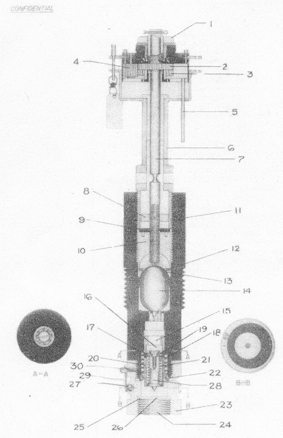
The M-123, M-124, M-125 tail fuzes are designed for any of the Army-Navy stan-dard general purpose and semi-armor piercing bombs. They are time fuzes which operate in 1, 3, 6, 12, 24, 36, 72 and 144 hours and are designed to render air-fields, dock and indurstrial installations inoperative for these periode of time. The fuze differ only in length of the arming stem cases. The fuze body is composed of three pieces – the stem case (6), upper fuze body (11), and lower fuze body (23). The stem case (6) which is threaded and staked to the upper fuze body (11), contains the gear assembly and the arming stem (7). The upper fuze body (11) contains cotton waste (15) and the acetone glass ampoule (14) which is broken by the arming stem (7) as it screws down in arming. The lower fuze body (23) contains the striker assembly and the M-19 primer-detonator (24). The stri-ker assembly consists of a spring loaded firing pin (28) which is held cocked by locking balls (19) bearing against a celluloid ring (17). The rest of the striker as-sembly consists of a firing pin sleeve (20) which is held spring loaded by locking balls (22) bearing against a flange on the lower fuze body (23). The bottom of the lower fuze body (23) is internally threaded to receive the M-19 primer-detonator (24). |
|
6 |
INSTALLATION |
|
|
a. Make sure that the upper fuze body (11) and the lower fuze body (23) are screwed together well, hand tight. Insert holder closing disc (aluminum) (26), hol-der sealing washer (lead) (25), and the M 19 primer detonator (24) in the base of the fuze. Tigthen these parts with a wrench marking sure that the anti-withdra-wal locking ball (27) or its groove is not damaged. |
|
|
b. Remove thumb screw (30) and ball clip (29). The anti-withdrawal locking ball (27) should move freely in its groove. At this point do not attempt to unscrew the upper fuze body (11) from the lower fuze body (23) as it will detonate. |
|
|
c. Screw fuze into the bomb by hand. Do not under any circumstances attempt to with-draw the fuze during or after it has been installed. Separation of the upper fuze body (11) from the lower fuze body (23) by as much as 3/64 od an inch will cause it to detonate. |
|
|
d. Remove the cotter pin and insert arming wire. Remove safety pin after arming wire is inserted. |
|
|
e. Install vanes and secure with the locking nut. Place two Palmstock clips over the end of the arming wire. |
|
|
f. The fuze should not be installed an appreciably long time before takeoff espec-ially if the temperature exceede 120 degrees F. |
|
7 |
FUZES LIKELY TO BE FOUND WITH |
None. The T 30 nose anti-disturbance fuze is in the process of development for usw with fuzes. |
|
8 |
COMPONENTS OF EXPLOSIVE TRAIN |
Primer-lead azide; Upper-lower detonator-tetryl. |
|
9 |
ARMING AND FUNCTIONING TIME |
These fuzes arm after 150-170 revolutions of the arming vane. Functioning time is determined by the concentration of the acetone solution and the use of extra celluloid discs. |
|
10 |
OPERATION |
|
|
The stem case (6) and gear system of this fuze is identical with that of the AN-M 100A2 fuze except that the arming stem (6) has a right hand thread so that it will screw down instead of out. The rotation of the break glass ampoule (14) filled with acetone. The acetone leaks into some cotton waste (15), then to a cellu-disc (16) (this disc is present only in fuzes with a delay or more than 12 hours), and then to a celluloid ring (17) which holds a spring loaded firing pin (28). When the celluloid ring (17) has been softened by the acetone the firing pin locking balls (19) are freed end the firing pin (28) is driven by its spring (21) into the primer-detonator (24). If the enemy at-tempte to withdrawn the fuze the anti-withdra-wal locking ball (27) will ride into the shallow part of its groove and jam against the wall of the adapter booster. This will cause the lower fuze body (23) to re-main locked in the bomb while the rest of the fuze is withdrawn. A separation of 3/64 of an inch between the upper fuze body (11) and the lower fuze body (23) will free the spring loaded firing pin sleeve (20) which will driven the firing pin (28) into the primer detonator (24). |
|
11 |
SPECIAL PRECAUTIONS |
|
|
a. Never against to withdraw the fuze during or after installation in the bomb. |
|
|
b. If bombs with this fuze is not dropped they must be jettisoned over enemy territory or in the sea. They cannot be considered safe even if dropped unarmed. |
|
|
c. The fuzes should not be subjected exceading 120° F. In each shipping box there are 2 vials containing powder which solidify at higher temperatures. Follow directions in the shipping box is regard to the use and the disposition of these fuzes if higher temperatures are experienced. |
|
|
d. In assembling the primer detonator care should be taken to avoid damage to the anti-withdrawal locking ball and its groove. |
|
|
e. The adapter booster (the part of the bomb into which the fuze is screwed) should be staked to the tail plug (this plug closes the end of the bomb) and the tail plug should be staked to the bomb case. This operation should be performed before the fuze is installed. |
|
|