|
|
|
ALLIED BOMBS AND FUZES |
| PART II - U.S. BOMB FUZES |
| A. ARMY FUZES |
|
FUZE DATA |
FILE NO.: 2142.B2 |
||
|
NATIONALY: U.S. Army. |
INFORMATION DATE: Sept. 1943 |
||
|
DESIGNATION: |
M-111, M-111A1, |
TYPE OF MISSILE: |
FLARE |
|
|
M-111A2 |
FUZE MECHANICAL TIME, M-111 |
|
|
CLASSIFICATION: |
Mechanical |
PRINICPAL MARKINGS: |
Flares, |
|
Time Nose Fuze - Aerial Burst |
Flash Bombs, Fragmentation |
||
|
|
|
MARKINGS |
|
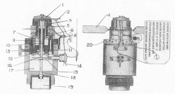
FLARE FUZE MECH. TIME M-111 appears on side of body. A graduated scale from 15 to 93 appears on the shoulder beneath the arming vanes. Subsidiary markings: P.A. 5-12, LOT 2205-2 are found on the body. |
|
BOMBS USED IN |
1. Parachute flare. |
|
|
DATA |
|
|
1 |
COLOR |
Unpainted aluminum. |
|
2 |
OVERALL LENGTH |
4.2 inches. |
|
3 |
OVERALL WIDTH |
1.6 inches. |
|
4 |
MATERIAL OF CONSTRUCTION |
Aluminum alloy except for steel striker which is zinc or cad- mium plated. |
|
5 |
PARTS |
|
1 |
Striker head |
11 |
Striker Shoulder | |
|
2 |
Vane locking device |
12 |
Cocking Pin | |
|
3 |
Safety Blocks |
13 |
Locking Screw | |
|
4 |
Arming Vanes |
14 |
Arming Pin | |
|
5 |
Stationary Gear |
15 |
Timing disc | |
|
6 |
Central arming gear (moveable gear) |
16 |
Striker | |
|
7 |
Idler Gear |
17 |
Timing clock mechanism | |
|
8 |
Safety Bracket |
16 |
Primer cap | |
|
9 |
Striker Spring |
19 |
Booster | |
|
10 |
Striker |
20 |
Scale for time setting |
|
6 |
DESCRIPTION |
|
The graduated scale for time setting (20) around the M-111 reads from 15 to 93 seconds. The fuze is divided into two parts: the lower portion contains the clock-work mechanism (17). The clockwork is prewound and has high-frequency type vibration. The timing disc (15) sets on top of the clockwork. There is a slot cut in the outer circumference of the timing disc. The spring-loaded arming pin (14) sets in this slot to prevent the disc from turning (safety feature). The upper part of the fuze slides down into the recess of the lower portion and is secured there by pressure exerted by the three set screws. The cocking pin (12) is located on the base of the upper portion and is connected by a series of levers to the timing disc and falls in a slot in the disc after a predetermined time has elapsed. The spring loaded striker (16) and the train of arming gears are housed in the upper portion. The striker head (1) screws into the striker spindle; three safety blocks (3) are placed under the striker head in an assembly like the M-110. There are two arming vanes (4) which operate the arming gears (5, 6 & 7). The lock screw (13) protru-des from one side of the fuze, and the arming pin (14) from the other. In addition to the arming pin, this fuze incorporates the safety bracket (8) which is attached to the vane assembly in one part and to body portion in the other part. The arm-ing wire the passes thru the arming pin and the two brackets, thus not only pre-venting the clock from working but also preventing the rotation of the vanes until the wire is withdrawn. |
|
7 |
POSITION AND METHODS OF FIXING IN BOMB |
The fuze is screwed into the nose of the bomb. |
|
8 |
FUZE LIKELY TO BE FOUND WITH |
Found alone. |
|
9 |
COMPONENTS OF EXPLOSIVE TRAIN |
The primer cup extends into the booster cup. The booster contains 70 grains of Black Powder. |
|
10 |
ARMING TIME |
570 revolutions of the vanes. |
|
11 |
OPERATION |
|
|
The time interval is set by turning the upper part of the fuze to the desired sett-ing on the graduated scale (20) indespendently of the lower portion and tighten-ing the lock screw (13). Upon being released from the plane, the arming wire is withdrawn releasing the vanes (4) and the arming pin (14). The vanes (4) rotate and at approximately 570 revolutions, the central arming gear (6) is withdrawn freeing the safety blocks (3) to fly out, and freeing the striker (10). As the arming pin (14) is released, the timing disc (15) starts rotating. After the predetermined set time hase elapsed, the slot in the disc is opposite the timing disc lever. Through a series of levers, pressure forces this timing disc lever to fall into this slot. This movement through this same system of levers frees the cocking pin (12) to rotate from under the shoulder of the spring cocked striker (10). With the safe-ty blocks (3) out, the striker is now forced down striking the primer cap (18). However, if the timing assembly should fall, the bomb would still detonate on im-pact, because the striker woulde be forced down, shearing any obstruction and firing the primer. |
|
|
DESIGNATION M-111A1 |
|
|
Changes from M-111. |
|
|
1. Changed setting time from 15 to 93 seconds to 5 to 93 seconds. Thus, aerial burst could take place 5 seconds after bomb was released. |
|
ARMING TIME FUNCTIONING TIME |
570 revolutions of the vanes. 5 to 93 seconds after release from plane. |
|
DESIGNATION M-111A2 |
|
|
1. Adapted horseshoe safety block instead of three safety blocks with grooves. Horseshoe collar held on by sleeve or central arming gear. |
|
|
2. Reduced number of teeth on gear-stationary gear gear reduced from 56 teeth to 33 teeth. Central arming (moveable) gear reduced from 57 teeth to 34 teeth. |
|
|
3. Strengthened gears. |
|
|
4. Vane construction-shorter, smaller, and stronger to facilitate packing. |
|
ARMING TIME |
340 revolutions of vanes. |
|
|
FUNCTIONING TIME |
5 to 93 seconds after release from plane. |
|
|