|
|
|
ALLIED BOMBS AND FUZES |
| PART II - U.S. BOMB FUZES |
| A. ARMY FUZES |
|
FUZE DATA |
FILE NO.: 2111.B7 |
||
|
NATIONALY: U.S. Army. |
INFORMATION DATE: Sept. 1943 |
||
|
DESIGNATION: |
M-110 |
TYPE OF MISSILE: |
Fragmentation |
|
|
AN-M-110A1 |
(anti-personnel) Bombs |
|
|
CLASSIFICATION: |
Mechanical |
PRINICPAL MARKINGS: |
Nose Bomb |
|
Impact - Nose Fuze |
Fuze M-110 |
||
|
MARKINGS: |
Nose Bomb Fuze |
||
|
M-110 found on body of fuze. |
|||
|
BOMBS USES IN: |
20 lb M-41 |
|
|
|
|
|
|
DATA |
M-110 |
|
1 |
COLOR |
Unpainted Aluminum. |
|
2 |
OVERALL LENGTH |
3.5 inches (with booster). |
|
3 |
OVERALL WIDTH |
Fuze body - 1.7 inches. |
|
4 |
MATERIAL OF CONSTRUCTION |
Steel safety blocks and striker; Aluminum body. |
|
5 |
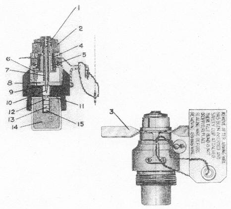
PARTS |
| 1 | Striker head | 8 | End Plate | |
| 2 | Safety Blocks | 9 | Retainer Pin | |
| 3 | Arming vanes | 10 | Striker | |
| 4 | Stationary gear | 11 | Washer | |
| 5 | Central arming gear (Movable gear) | 12 | Primer | |
| 6 | Idler Gear | 13 | Upper detonator | |
| 7 | Striker spring | 14 | Lower detonator | |
| 15 | Booster |
|
6 |
DESCRIPTION |
|
|
The body is divided into two pieces. The upper piece houses the striker assembly with the striker head (1), striker (10), spring (7), the three safety blocks (2), the two arming vanes (3), and train of gears which arm the fuze. The three safety blocks (2) are located between the striker head (1) and the body. These blocks have a groove on the inside of which fits over the shaft of the central arming gear (5). The upper part of the body screws into the lower portion of the body. The lower portion houses the primer (12) and is threaded internally and externally at the base. The internal threads are to receive the booster cup and the external to screw the fuze into the bomb. The arming vanes are prevented from rotating by an assembly which is hooked to the vanes in one part and the other hooked to the lower part of the body. These two pieces are held in place by the arming wire. |
|
7 |
POSITION AND METHOD OF FIXING IN BOMB |
The fuze screws into the nose of the bomb. |
|
8 |
FUZES LIKELY TO BE FOUND WITH |
Always found alone. |
|
9 |
COMPONENTS OF EXPLOSIVE TRAIN |
|
|
The primer is located in the lower housing; the flash from this primer sets off the detonator retained in the cup screwed into the base of the fuze. The cup also contains the tetryl booster. |
|
10 |
OPERATION |
|
|
Upon being released from the plane, the arming wire is withdrawn allowing the vanes (3) to rotate. The rotation of the vanes transmits motion to the gears. The central arming gear (5) which holds the safety blocks (2) is withdrawn into the channel of the body, and after approximately 570 rotations of the vanes (3), the gear (5) is withdrawn enough to allow the safety blocks (2) to fall free and the fuze is armed. Upon impact, the striker (10) over-comes the creep spring (7) and impacts the primer (12) which detonates the booster (15) and filler of the bomb. |
|
11 |
ARMING TIME |
570 revolutions of vanes. |
| AN-M 110A1 | |
| Changes from M-110 |
| (1) |
Reduced number of teeth on gear – stationary gear reduced from 56 teeth to 33 teeth. |
|
| (2) |
Has horseshoe disc rather than there safety blocks. Central arming gear does not fit in groove in horseshoe disc, but sleeve prevents disc from flying out until it is lowered. |
|
| (3) | Vane construction – shorter, smaller and stronger to facilitate packing. |
|
12 |
ARMING TIME |
340 revolutions of vanes. |
|
|