|
|
|
ALLIED BOMBS AND FUZES |
| PART II - U.S. BOMB FUZES |
| A. ARMY FUZES |
|
FUZE DATA |
FILE NO.: 2111.B4 |
|
|
NATIONALY: U.S. Army. |
INFORMATION DATE: September 1943 |
|
|
DESIGNATION: |
PRINCIPAL MARKING |
NOSE BOMB FUZE M105 |
|
M 105 |
CLASSIFICATION |
Mechanical Impact Nose Fuze |
|
|
TYPE OF MISSILE |
H.E. Bombs |
|
|
|
MARKINGS: |
BOMBS USED IN: |
|
NOSE BOMB FUZE M 105 Appears on the body and
the vanes. Deep Slot Delay; Shallow Slot Inst. appears on fuze body
around setting pin. Subsidiary markings: |
Only the modified mark series bombs. |
|
|
DATA |
M 105 |
|
1 |
COLOR |
Unpainted metal |
|
2 |
OVERALL LENGTH |
4.3 inches |
|
3 |
OVERALL WITDH |
|
|
|
Body |
2.7 inches |
|
4 |
MATERIAL OF CONSTRUCTION |
The body, striker assembly, and safety discs are of cadmi- um plated steel. Gear train and arming vane hub is of brass. The detonator cup may be of brass or plated steel. |
|
5 |
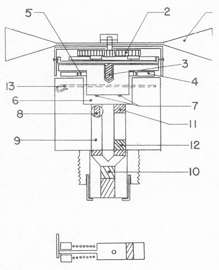
PARTS |
|
1 |
Arming Vanes |
8 |
Setting Pin and Slide | |
|
2 |
Gear Reduction System |
9 |
Instantaneous Channel | |
|
3 |
Arming Screw or Spindle |
10 |
Detonators | |
|
4 |
Safety Discs |
11 |
Primer (delay) | |
|
5 |
Steel Spring |
12 |
Delay | |
|
6 |
Striker Block Assembly |
13 |
Shear Wire | |
|
7 |
Strikers (2) |
|
6 |
DESCRIPTION |
|
|
The upper assembly of the fuze includes the 2 vanes and a train of reduction gears (2). The reduction gears are set to be threaded arming spindle (3) which screws into the top of the striker block (6). A cap fits down around the striker block. A series of safety discs (4) are inserted between the striker block shoulder and the fuze body. There are 2 striker points (7) at the base of the striker block. A brass shear wire (13) passes through the fuze body and the striker block. The fuze body has a hollow recess in the upper portion to receive the striker block. At the bottom of this recess and directly beneath the 2 strikers are 2 channels which lead to the detonator. The delay channel contains a cap with a delay and realy elements; the instantaneous channel contains a cap only which is attached to the setting pin (8). The setting pin protrudes on the outside, and if turned to instan-taneous, then the cap is directly beneath the striker; but if set for delay, then the cap is turned away from the striker leaving only a hollow channel booster. The base of the fuze body is threaded internally to receive the detonator cap and ex-ternally to screw into the bomb. |
|
7 |
POSITION AND METHOD OF FIXING IN BOMB |
The fuze screws into the nose of the bomb hand tight. |
|
8 |
FUZES LIKELY TO BE FOUND WITH |
M 106, M 100, M 101, AN-M 100A1, AN-M 101A1, M 102, AN-M 102A2 AN-M 100A2, AN-M 101A2, AN-M 102A2 |
|
9 |
COMPONENTS OF EXPLOSIVE TRAIN |
No. 4 Primer cane are used to initiate both trains of explo- sive. The delay channel and detonator assembly are as fol- lows: delay train of 0.32 grain of black powder, the relay change of 1.47 grains of lead azide. |
|
10 |
OPERATION |
|
|
Upon being released from the plane, the vanes (1) are free to rotate. After 720 rotations of the vanes, the arming screw (3) is withdrawn from the striker block (6) and the cap and arming vanes fall free of the fuze. The safety discs (4) falls away and the fuze is armed. Upon impact, the striker block (6) is forced down cutting the shear wire (13) and bringing the striker points in contact with the firing assembly. If the fuze is set for instantaneous action, then the flash from the cap sets off the detonator and detonates the bomb before the delay can func-tion. But if the fuze is set for delay action, then the striker point over the instan-taneous channel merely contacts the empty recess with no effect; and the delay cap is fired setting off the delay and relay element, the detonator, and the bomb filler. |
|
11 |
Remarks |
This fuze is obsolete, and will not fit in any bombs, but mo- dified mark series. |
|
|