|
|
|
ALLIED BOMBS AND FUZES |
| PART II - U.S. BOMB FUZES |
| A. ARMY FUZES |
|
FUZE DATA |
FILE NO.: 2111.B2 |
||
|
NATIONALY: U.S. Army. |
INFORMATION DATE: Sept. 1943 |
||
|
DESIGNATION: |
AN-M 103 |
TYPE OF MISSILE: |
All G.P. H.E. Bombs |
| M-103 | of the M series | ||
|
CLASSIFICATION: |
Mech. impact, |
MARKINGS: |
Nose bomb fuze |
| nose fuze. | M-103. These | ||
|
markings appear on the vanes and flanges of the fuze. In addition marks will appear: P.A. 9-38, LOT 1234-5. |
|||
|
|
|
|
DATA |
|
|
1 |
COLOR |
Unpainted metal. |
|
2 |
OVERALL LENGTH |
7.0 inches (with booster). |
|
3 |
OVERALL WIDTH |
2.7 inches (body). |
|
4 |
MATERIAL OF CONSTRUCTION |
All parts are cadmiumplated steel or brass. |
|
5 |
PARTS |
|
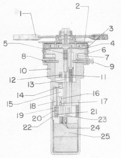
1 |
Arming vanes. |
13 |
Instantaneous striker. | |
|
2 |
Gear reduction system |
14 |
Primer | |
|
3 |
Vane cup screw (not on M 103 but is on AN-M 103) |
15 |
Compression chamber | |
|
16 |
Delay | |||
|
4 |
Strikerblock assembly |
17 |
Relay | |
|
5 |
Arming screw |
18 |
Compression cavity | |
|
6 |
Safety disc |
19 |
Primer | |
|
7 |
Steel spring |
20 |
Upper detonator | |
|
8 |
Shear wire |
21 |
Lower detonator | |
|
9 |
Setting pin |
22 |
Detonator slider springs | |
|
10 |
Fuze body |
23 |
Detonator slider | |
|
11 |
Arming stem |
24 |
Closing up charges | |
|
12 |
Delay striker |
25 |
Booster (tetryl) |
|
6 |
POSITION AND METHOD OF FIXING IN BOMB |
The fuze is screwed into the nose fuze pocket, using the external threads on the fuze body. |
|
7 |
EXPLOSIVE TRAIN |
For instantaneous action – primer, upper detonator, lower detonator, closing cup charges and booster. |
|
|
For short delay – primer, compression chamber, delay, re- lay, primer, upper detonator, lower detonator, closing cup charges and booster. |
|
|
8 |
FUZES LIKELY TO BE FOUND WITH |
M-100, M-101, M-102, AN-M-100A1, AN-M-101A1, |
|
9 |
ARMING TIME |
Instantaneous:– 850 revolutions of the vanes, or 2241 feet of air travel. |
|
|
Delay:– 525 revolutions of the vanes or 1494 feet of air travel. |
|
|
10 |
FUNCTIONING TIME |
Instantaneous. |
|
|
Delay – .10 second. |
|
|
11 |
PREARMING FOR DIVE BOMBING |
Rotate arming vanes 250 revolutions in a clockwise direc-tion or rotate arming vanes until 1/8 inch of the safety discs are exposed, which-ever occurs first. |
|
12 |
OPERATION |
This fuze is selective short delay or instantaneous functio- ning time, such selections may be made after the fuzes bomb is in the plane. By inserting the setting pin (8) pre- vents the arming stem from rising too high by engaging the shoulder on the arming stem. In this position, the arming stem extends down far enough to catch the spring loaded detonator slider on the first step and line up the delay fir- ing train. A spring loaded detent locks the slider in this po- sition. Instantaneous action is accomplished by rotating the setting pin 90 degrees and inserting it in the shallow slot. This permite the arming stem to rise until its shoulder rests against the top of the cavity. This frees the detonator sli-der (22) to move over under its spring pressure until the firing train is lined up under the instantaneous striker (12). In this position the detonator slider is locked by a spring loaded detent. |
|
|
When the bomb is released from the plane, the arming wire is withdrawn, permitting the arming vanes (1) to rotate. As the rotation of the arming vanes is transmitted through the gear reduction system (2) (gear reduction equals 65 revolu-tions of the vanes to 1 turn of spindle) the arming screw (5) is unscrewed from the striker block assembly (4), thus causing the vane cup to rise. When the vane cup has risen sufficiently, the safety discs (6) are forced to fly out of fuze by a steel spring (7). As the vane cup rises, the ar-ming stem (11) rises until its shoulder rests on the setting pin (9) (delay) or until it rests on the top of the cavity (in-stantaneous). This action does not take place until the base plate of the internal or lower gear has risen sufficient-ly to permit this, since the top of the arming stem is held down by this base plate. The vanes may continue rotating until the vanes, vane cup gear reduction system and arming screw fly off. At this stage, the striker block assembly is held in the fuze body by a shear wire (8) and the setting pin (9). On impact the striker block assembly (4) is driven down, shearing the shear wire (8) and the setting pin (9), and forcing the striker (13) into the firing train. (Delay or instantaneous functioning depending on position of setting pin.) |
|
|
13 |
REMARKS |
This fuze is not suitable for dive bombing unless it is pre- arming. It should never be used for masthead bombing. |
|
|
The AN-M-103, a modification of the M-103, is suitable for dive-bombing. |
|
|
|
Differences between M-103 and this AN-M-103. |
|
1. |
Changed number of threads on arming screw from 15 single to 6½ double. |
|
|
2. |
Changed vane construction, smaller and stronger vanes. |
|
|
3. |
Has loose fitting lug through fuze body in striker to pre- vent striker from pulling out on low angle impact. |
|
|
4. |
Contains screw threaded in cup that rides around groove in internal or lower gear. |
|
|
5. |
AN-M-103, arming time. Instantaneous 330 revolutions. Delay 220 revolutions. |
|
|
6. |
Note: Do not pre-arming this fuze. This fuze is suitable for dive bombing – but not for masthead bombing. |
|
|