|
|
| HANDBOOK OF ENEMY AMMUNITION |
| PAMPHLET No. 13 |
| GERMAN ROCKETS, GUN AND MORTAR AMMUNITION |
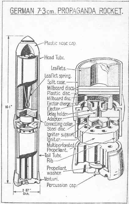
| GERMAN 7.3 cm PROPAGANDA ROCKET |
| (Fig. 15) |
|
This rocket is designed for dispersing propaganda leatflets, but the projector from which it is fired has not been identified. The overall length of the complete round is 16.1 in-ches, its maximum exetrnal diameter 2.87 inches and, including leatflets (weighing 8 oz.), weighs 7 lb. 2 oz. It is fired by percussion and fitted with base venting venturis, half of which are inclined to rotate the rocket in flight. "Pr.G. 41" is painted on the lid of the me-tal box container which holds 4 complete rounds. |
| The rocket consists mainly of:– |
|
Nose cap. |
|
Head tube with split case to accommodate propaganda leaflets. |
|
Ejector with fixed delay. |
|
Connecting collar. |
|
Tail tube containing propellant charge and ignition system. |
|
Venturi block with percussion cap. |
|
The nose cap is of plastic material weighing 4 oz. shaped to a low crh. and slightly redu-ced in diameter near the base end, which fits into the head tube. The cap is easily de-tached from the tube for insertion of reading matter. |
|
The head tube is a steel cylinder 7.48 inches in length and open at both ends. The ex-ternal and internal diameters are 2.56 inches and 2.36 inches respectively. Internally, at the forward end, the diameter is slightly increased to receive the nose cap which fits against a shoulder. The rear end of the tube is screwthreaded externally to enable the head and tail tube to be united by means of a connecting collar. |
|
The leaflets are rolled and contained in a split case which is a sliding fit in the head tube. The split case is held between the base of the nose cap at the forward end and two mill-board discs above a plastic disc at the base. The discs act as a piston in ejecting the leaflets. A light V-shaped spring held in compression fits into the centre of the roll of leaflets. |
|
The ejector unit is housed immediately below the plastic disc; it consists of a short brass tube with an internal diaphragm separating a top and bottom chamber. The chambers are connected by a communicating hole in the diaphragm displaced from the centre. |
|
The forward chamber contains the ejection charge consisting of approximately 1.13 drams of gunpowder and is closed by a millboard disc. The rear chamber is screwthrea-ded internally and houses a delay holder. The delay holder is screwthreaded externally and, in its upper surface, provided with a circular groove filled with a delay composition of slow match. The delay composition is in communication with the ejector charge and the central flash hole in the base of the holder. No vox washer is used to cover the delay composition and no escape is provided for the products of combustion. The time of burn-ing is not dajustable. The flash hole in the base of the holder is screwthreaded to receive a short tubular adapter, filled with gunpowder, which also screws into a steel disc fitted into the head of the tail tube. |
|
The connecting collar unites the head and tail units. It has an internal flange formed near its centre and is screwthreaded internally to receive the head and tail tubes. |
|
The tail tube is 6.35 inches in length and of similar wall thickness and bore so that of the head; it is screwthreaded internally at each end and, at its forward end, provided with an internal flange spun over to form a groove in its under side. At the venturi end, the internal surface is chamfered. |
|
A steel disc 0.4 inch thick with a stepped upper surface, fits into the head of the tail tube so that the step bears against the internal flange of the tube. The disc is bored centrally and screwthreaded to receive the adapter. |
|
Below the steel discs is an igniter support. The support
consists of a washer with a ring, |
|
The igniter consists of a pressed pellet of gunpowder contained in a circular flat alumini-um capsule 1.17 inches in diameter, with its open side facing the propellant. |
|
The propellant charge consists of a single cylindrical stick of propellant with a central axial hole surrounded by eight annular holes throughout its length. The stick weighs 15 3/4 oz., is 5.24 inches long and 2.25 inches in diameter. Three longitudinal ribs are form-ed on the propellant when extrudes from press. It is presumed that they are designed to fix the charge during transport and centralize it for ease of ignition. There are no metal grids. The main stick of propellant is held of the venturis by a small washer of propellant approximately 0.16 inch thick and 1.06 inches diameter of the same composition as the main charge, cemented to the base of the propellant. |
|
A provisional analysis of the propellant is as follows, nitrocellulose 60.6 per cent, digly-coldinitrat 32.9 per cent, akardite 0.8 per cent, graphite 0.2 per cent, ash (carbonated) 0.7 per cent, and undertermined matter 4.8 per cent. |
|
No auxiliary materials are employed to transmit the flash from the percussion cap to the igniter. |
|
The venturi block is screwthreaded internally for attachment to the tail tube and is chamfered at the base. It is provided with 14 coned venturis arranged in two concentric circles of seven in each, and a central hile bored in three diameters to house a percus-sion cap. The outer ring of venturis hase a throat diameter of 0.118 inch and are inclined about 30 degrees, while those forming the inner ring have a throat diameter of 0.138 inch and are not inclined. The full angles of the emergent cones are about 30 degrees. Not attempt has been made to seal the venturi end of the tail tube. |
| Action |
|
On the percussion cap being struck, the flash passes through the central hole in the pro-pellant to the igniter which ensures complete ignition of the propellant charge. The igni-ter also ignites the priming composition in the adapter, which in turn ignites the delay composition. Pressure set up inside the rocket and escaping through the venturis propels the rocket forward, the inclined outer ring of venturis causing the rocket to rotate. |
|
The delay composition burns until such time as it ignites the ejector charge. Gas pres-sure from the ejector charge forces the disc forward to expel the contents of the head tube. As the split case emerges it falls apart allowing the spring to scatter the leaflets. |
|
|
|
|