|
|
| HANDBOOK OF ENEMY AMMUNITION |
| PAMPHLET No. 11 |
| GERMAN MINES, GRENADES, GUN AMMUNITION AND MORTAR AMMUNITION |
| GERMAN MECHANICAL TIME AND PERCUSSION FUZE S/90/45 |
| (Dopp.Z. S/90/45) |
|
The fuze has a mechanical time action with a maximum time of running of 90 seconds and a graze action of the normal German type. The time mechanism appears to be a 45 second mechanism modified by a change in the ratio of the gear train and an increase in the strength of the main spring. The fuze is possibly used as an alternative in the H.E. shell (K.Gr. 39) and the H.E.B.C. shell (K.Gr. 38 (Hb)) for the 17 cm K. in Mrs.Laf. The weight of the fuze is 1 lb. 12 oz. |
|
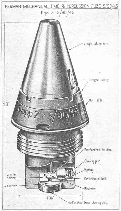
In external appearance the fuze consists of a flat topped cone-shaped head of aluminium secured to a dull steel body near its base by a bright alloy securing ring. The upper part of the body is coned above the flange to match the head. Below the flange it is screw-threaded for insertion in the shell and below the thread there is plain cylindrical portion. The designation of the fuze "Dopp.Z. S/90/45", is stamped in the body above the flange. Rectangular key slots for setting are formed in the head and the body and a setting ar-row for percussion action is engraved in the head adjacent to the slot. When inserted in the shell the fuze protrudes to the extent of approximately 3 inches. The diameter of the screwthreaded part is 1.96 inches. |
|
|
| Body |
|
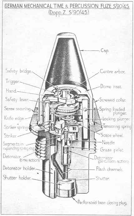
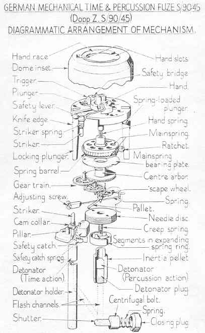
The body is recessed at the base to accommodate the shutter assembly and, equally spaced around the recess, there are three vertical channels for the bolts securing the time mechanism unit. An additional vertical channel, closed at the base by a screwed plug, accommodated the holder of the detonator for the time action. A radial channel in the wall of the recess contains a brass centrifugal bolt and is closed at the outer end by a screwed plug. A portion of the top of the recess is cut away to permit movement of the bolt and a flash channel in the centre of the top connects with a recess in the upper part of the body. |
|
The upper recess contains the graze pellet of the percussion mechanism and is connec-ted to the channel containing the detonator for the time action by an inclined channel which enters the recess near its base. Near the top, the recess is enlarged to form a platform on which four centrifugal segments of brass are fitted on steel pivots. Above this the recess is screwthreaded to receive the percussion needle holder. The coned flanged top of the body is recessed to form a platform for the time mechanism unit and is screwthreaded internally to receive the securing ring for the aluminium head. Two holes, diametrically opposite are formed in the platform to receive the locking plungers of the time unit. There is also locating stud for the unit and a circular seating for a presspahn washer. Four small screws are inserted through the coned flange to lock the securing ring when the fuze is tensioned during assembly. |
| Percussion Mechanism |
|
The graze pellet, carrying an igniferous detonator secured by a perforated screwed plug, is of brass with a shoulder near the top which is engaged by the four centrifugal brass segments. The segments are retained in a position overlapping the pellet by an expand-ing spring ring. A spiral creep spring is fitted between the pellet and a needle holder which consists of a steel disc screwed into the top of the recess containing the graze meachanism. The needle protruding from its underside has a pyramid shaped point. |
| Shutter Assembly |
|
The assembly contained in the lower recess in the body consists of a copper plate shut-ter moving in a guideway formed in the top of a cylindrical aluminium holder. The holder has a central flash hole and is recessed at one side for the centrifugal bolt which under the pressure of its spiral spring, bears against the outer end of the shutter and keeps the shutter in a position masking the flash hole in its aluminium holder. The centrifugal bolt is a cylindrical pellet of brass with a recess at its outer end to locate the inner end of its spiral spring. The outer end of the spring is held under compression by the screwed plug closing the radial channel in the wall of the recess and located by a circular groove in the inner face of the plug. A thin disc of tin with a central flash hole and with part of its circumference cut away for the centrifugal bolt is placed on top of the shutter holder. The recess containing the shutter assembly is closed at the base by a screwed plug which has a central flash hole. The flash hole is closed by a thin disc of tin fitted bet-ween the inner face of the plug and the base of the shutter holder. |
| Head Assembly |
|
The flat topped aluminium head is in the shape of a cone with a cylindrical portion near the base. An external flange formed at the base which supports the tensioning wire. The underside of the flange is cut away at four places to receive corresponding projections at the base of the dome. The dome, fitted inside the head, is of aluminium and is in the form of an inverted cup which fits over the time mechanism unit and is keyed to the flan-ge at the base of the aluminium head by for projections at its base. The inside of the top of the dome is shaped to form a hand race against which the hand on the top of the time unit bears, when rotating. Part of the race is cut away so that the hand can be pushed upwards by its spring when in alignment with the slot so formed. |
|
The head of the fuze is secured to the body by a securing ring which screws into the in-ternal screwthread above the flange. Between the base of the securing ring and the flange at the base of the head there is a length of waved spring wire which is compres-sed between the ring and the flange when the ring is screwed down. By this means the tensioning of the head is adjusted during assembly so that it can be turned for setting but will not strip. |
| The Mechanism Unit |
|
The time mechanism is assembled in a cylindrical unit of super-imposed brass plate with an aluminium hand on the top and two locking plungers in slots cut down diametrically opposite sides of the cylindrical assembly. The plungers are comparatively weighty and consist of steel strips tapering towards the base on the inner side. On the outer side of each, approximatelly at the centre, a projecting vertical knife edge is formed. A spring loader ball protruding from one side of the plungers engages a corresponding recess in the slots and thus supports the plungers which protrude below the base of the unit into recesses in the fuze body. |
|
The mechanism is similar to that in the S/30 and S/60s fuzes, that is, it consists princi-pally of a spring loaded striker held off the detonator by an eccentric cam collar on the striker which is supported by a pillar and a centrifugl safety catch. The cam collar is kept in this position by a safety lever which fits over flats formed on the forward end of the striker and is held by the ring shaped centre of the hand. The hand, with a spiral spring beneath it, is keyed to rotate with the centre abror under the control of a train of gear wheels and an escapement and, before firing, is held by the privoted trigger. Adjacent to the trigger a safety bridge is fitted which overlaps the hand to prevent functioning at settings of less than approximately one second. The spring plunger supporting the trigger engages in the end of trigger instead of the outer side, as with the S/30 and S/60s fuzes. The use of a stronger main spring, which is of wider strip than the original, has resulted in the use of a thin steel disc instead of the normal base of the spring barrel to support the spring. |
|
|
| Time Action |
|
The time of running is governed by the size of the arc extending counter-clockwise bet-ween the position of the hand when held by the trigger and the position of the slot in the dome hand race. The fuze is set by turning the head with the aid of a setting device which consists of a graduated ring surrounding a moveable ring on which there is a set-ting index and a handle. The device is placed over the fuze, and the outer ring, bearing the graduations, is clamped by a key engaging in the key slot above the flange in the fuze body. A key in the inner ring, bearing the index, engages in the key slot in the head of the fuze. The inner ring is then rotated by means of its handle until the index is alig-ned with the required graduation and takes with it the head of the fuze. The dome inset with the hand race formed in its upper part, is rotated with the head to the set position. The turning of the head is retarded by the waved wire tension spring between the secur-ing ring and the flange at the base of the head. |
|
On acceleration the two tapered locking plungers set back into the recess in the top of the body. As their wider positions with the protruding knife edges move back through the slots, the knife edges cut into the wall of the dome and thus prevent rotation of the dome relative to the mechanism unit. At the same time, the trigger hinging on its pivot set back and releases the hand. The small spring loaded plunger in the trigger is then free to emerge and thus prevents the trigger rebounding. The release of the hand enab-les the main spring to rotate the centre arbor under the control of the escapement. The hand, rotating with the arbor, moves clear of the safety bridge and is pressed up against the hand race in the top of the dome by the sprial spring in the top of the arbor beneath the hand centre. |
|
During flight, the safety catch the swung clear of the cam collar on the striker by centri-fugal force and the striker is then supported only by the pillar. When the rotating hand reaches the slot in the hand race it is forced upwards by its spring and thus releases the safety lever keyed to the top of the striker. The striker, with the lever, is then rotated by the pressure of its spring combined with the effect of the inclined surface on the cam collar bearing on the pillar so that the collar moves clear of the pillar. The striker is driven away from the safety lever by its spring and pierces the detonator. The flash from the detonator, directed by the shape of the detonator holder, passes into the lower part of the recess containing the graze pellet and follows the same course as that described for the percussion action. |
| Percussion Action |
|
When set for percussion the arrow on the head of the fuze coincides with the index line on the securing ring and the key slots in the head and body are in alignement. At this setting, the slot in the hand race of the dome is masked by the safety bridge, so that although the hand is released when acceleration occurs, it cannot rise through the slot to release the safety lever and the striker. |
|
During flight the coil of the expanding spring ring, surrounding the segments engaging the shoulder of the graze pellet, is enlarged and the segments are swung clear of the pellet by centrifugal force. At the same time the centrifugal bolt is thrown outwards, compres-sing its spring, and the shutter opens. |
|
On graze, the graze pellet overcomes the creep spring by its momentum and carries the detonator forward to be pierced by the needle. The flash from the detonator passes through the hole in the base of the recess, through the channel exposed by the open shutter, perforates the thin disc and emerges through the hole in the screwed plug at the base of the fuze. |
|
|
|
|