|
|
| HANDBOOK OF ENEMY AMMUNITION |
| PAMPHLET No. 8 |
| HUNGARIAN MINE |
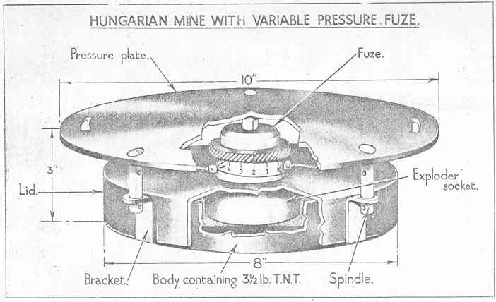
| HUNGARIAN MINE WITH VARIABLE PRESSURE FUZE |
| (Fig. 25) |
|
The mine, which is used by the Germans and probably by the Italians also, has been re-ferred to as the C.R.T. type (these letters indicating the manufacture are stamped in the base) and is also known as the C.V.P. 1. The latter is now the standard designation. |
|
The variable pressure fuze, which can be set to function undo various loads or by trip action, enables the mine to be used as an anti-tank or an anti-personnel mine. |
| The mine is painted black and consists of the following main parts:– |
|
Body with 3.5 lb. filling of cast T.N.T. |
|
Lid which fits over the body with fuze-hole socket and three brackets for the spindle of the pressure plate. |
|
Pressure plate with three spindles. |
|
Variable pressure fuze. |
| The weight of the mine is approximately 8 lb. |
| Body and Bursting Charge |
|
The cylindrical body is in the form of a dish with a diameter of 8 inches and is a cold pressing from 0.03 inch dead mild steel sheet. The bursting charge is contained in a black paper carton and consists of a 3.5 lb. cast block of T.N.T. |
| Lid |
|
The cylindrical lid is in the form of an inverted dish which fits closely over the body and carries both the fuze and the pressure plate. Cold pressed from 0.04 inch dead mild steel, it has a screwthreaded brass fuze-hole bush sweated into a hole in the centre at the top and has three equally spaced right-angle brackets welded to the side. The brac-kets are of 0.12 inch mild steel and each has a hole in the horizontal arm to receive a corresponding spindle on the pressure plate. A socket is formed below the fuze-hole to receive an exploder pellet. |
| Pressure Plate |
|
The pressure plate, supported by the fuze, is 10 inches in diameter, slightly domed and is stamped from hot-rolled mild steel 0.12 inch sheet. Three equally spaced mild steel spindles of 0.4 inch diameter are welded into holes near the periphery of the plate and project downwards. Two holes, about 1 inch apart, are formed in the spindles to receive a pin when the spindles are inserted through the brackets on the lid. The pins are inser-ted in the upper holes, below the brackets, when the mine is plugged and packed and in the lower holes when fuzed ready for use. Two rectangular slots are formed in the pres-sure plate, diametrically opposite, to receive a tie arrangement used in packing. |
 |
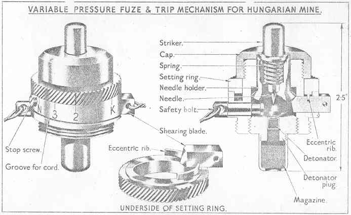
| Fuze (Fig. 26) |
|
The fuze is mainly of brass and consists of a cylindrical body with a graduated flange and a milled setting ring around its approximate centre, below which a brass safety bolt pro-trudes from one side and a steel shearing blade from the other. A small magazine is screwed to the base of the fuze and a brass cylindrical striker prodrudes from the centre of the top. |
|
The fuze is designed so that the needle is held off the detonator by a steel shearing blade which engages a tapered flange on the needle holder. When the requisite load is applied to the striker the flange is cut by the blade and the needle pierces the detona-tor. The load required depends upon the extent to which the blade is engaging the need-le holder, and this can be varied by the setting ring. The fuze can also be used as a trip mechanism by setting so that there is no obstruction to the withdrawal of the shearing blade by a connected trip wire. |
|
The brass body has a flange or platform formed around its centre, which has a cicular groove of square section in its upper face to receive the setting ring and is graduated around the periphery for setting. A groove is also formed in the periphery to receive a length of cord attached to the safety bolt. The lower part of the body is screwthreaded externally for insertion in the lid of the mine and internally to receive the detonator ring. The upper part is screwthreaded externally to receive the brass cap which retains the striker. A large recess in the body contains the needle holder and has two radial channels near the base for the safety bolt and shearing blade. |
|
The brass striker is in the form of a plunger which protrudes through the cap and is sup-ported by a steel spiral spring held in compression between the needle holder and an ex-ternal flange on the striker. |
|
The brass needle holder is cup-shaped to receive the striker and spring and has a tape-red flange around its base. The steel needle is fitted in its base, which is recessed to engage a flange on the inner end of the safety bolt if the holder is not supported by the shearing blade. |
|
The brass safety bolt is located below the level of the shearing blade, and the flange at its inner end does not engage the recess in the base of the needle holder unless the blase is not supporting the holder. When engaged by the holder the bolt cannot be with-drawn. A 3-foot length of cord is attached to an eye in the outer end of the bolt and is secured round a groove in the graduated flange on the body. |
|
The shearing blade is of hardened and high-tempered carbon steel and is shaped as a cutting tool. An eye is formed in its outer end for the attachment of a trip wire, and a groove in its upper face is cut to the same pitch as the rib on the underside of the set-ting ring, with which it engages. |
|
The brass setting ring fits round the body, where it is retained between the graduated flange and the cap. The exterior is milled to facilitate turning and has a setting index in the form of a red vertical line. The underside of the ring is stepped to enter the groove in the flange. A rib, extending eccentrically over a portion of the base of the ring, protrudes through a slot in the groove and engages the groove in the upper face of the shearing hole. |
 |
| Action |
|
The mine is transported with a wooden plug in the fuze-hole, the fuze being set and in-serted when required for use. The pressure plate is then fitted to the mine and the safe-ty bolt withdrawn by its cord. The turning of the setting ring causes the eccentric rib on its underside to impart a lateral movement to the shearing blade, thereby determining the load required to result in the shearing of the tapered on the needle holder. |
|
When the requisite load is applied to the pressure plate the striker is pushed down against its spring and the stress is taken by the needle holder. This results in the shear-ing of the tapered flange on the holder and the needle pierces the detonator. |
|
The loads required to function the fuze at the various settings are as follows:– |
| Setting |
Load |
||
| K |
77 lb. |
||
| 1 |
220 lb. |
||
| 2 |
440 lb. |
||
| 3 |
660 lb. |
||
| N |
770 lb. |
|
The H setting is used when the fuze is required to function as a trip mechanism when the stop screw, adjacent to the safety bolt in the graduated flange has been removed. With the screw removed and the setting ring turned to the H setting, the eccentric rib is dis-engaged from the groove in the shearing blade. The blade is then free to be withdrawn by a trip wire attached to its outer end. |
|
|